
LITTLE ABOUT THIS C.G.N. NETWORK
California GMRS Network
California GMRS Network is a network of G.M.R.S. Radios, remote base stations and hot spots "NODES" accessible to each other via Voice over Internet Protocol. California GMRS Network runs on a dedicated computer (including the Rasperry Pi) It is based on the open-source Asterisk PBX running our App, RPT., App, RPT. makes Asterisk a powerful system capable of controlling one or more radios. It provides linking of these radio "nodes" to other systems of similar construction anywhere in the world via VoIP.
California GMRS Network primary use is as a dedicated computer node wired to Our radio's (NODES). Connections from Californiagmrsnetwork.org, And other VoIP clients. Around The World! (G.M.R.S.) = GENERAL MOBILE RADIO SERVICE=
THIS IS AN OPEN NETWORK JUST BE NICE!
NOW YOU CAN DOWNLOAD IMG. & PROGRAMS TO LOAD AN SD CARD
TO JOIN THE CALIFORNIA GMRS NETWORK FAMILY AND THE WORLD!
ANY ONE IN THE WORLD CAN USE THIS! See Videos below for how to on build your Node!
(((If that's to your liking!))) And Added Pic's, plus some links to help find things.
{TO JUST ABOUT PLUG N PLAY}
See Bellow Sample Pic's for Link's and more of My
New Video's
ASAP
New Video's to come.
There is some step-by-step information Just have to email to get a node Number.
Have your name your call and is it repeater or simplex ready!
CAN {{NOT}} Scan for Viruses ((NOT)) A windows Program
((PLEASE READ THE {{{READ FIRST}}} FILE))
USE EITHER ONE
NEW Download 12=2=25
((Talk Soon!))
Click Download For Node Setup And Files

WE ARE THE CALIFORNIA GMRS NETWORK, KNOWN ALSO AS C.G.N.

WE ARE LOOKING FOR HILL TOPS TO ADD REPEATERS ON! can be 100% off grid if in right place.
We Are
Just a group of likeminded people That enjoy radio communications. This is the GMRS, (GENERAL MOBILE RADIO SERVICE)

The California gmrs Network is a link of Simplex radios connected to Hubs and the hubs are connected to other hubs across the country to give us access from the east coast of the United States to the farthest west of the United States the Hawaiian Islands and Through the Links We talk to United Kingdom. And the Country of Brazil, And the World!
RX.462.600+ Pl,69.3
DEC. & NEC.
This is another California g m r s network repeater built by ME lee (wrex300)

THIS REPEATER IS OWEND BY
Tulare County Amateur Radio Club. Of Visalia. CA. NOT LINKED TO CGN DO TO TCARC NOT WANTING TO
Called TC1GMRS
Located On Park Ridge East of Fresno. CA. East of Grant Grove in The Kings Canyon National Park Next to Park Ridge Fire Look Out at About 7535 Feet
N36'43'28.8"
W118.56' 36.6"
(((462.700))) + Offset
Pl 103.5
REPEATER IS ON A SMALL BATTERY!
AND SOLAR PANEL
Delilah Ridge
CLICK HERE FOR CAM LINK
100% Solar Power
PRIVATE PROPERTY
DELILAH (1) Or (L-1) 462.650 + off
T-DCS D025N & R-DCS D025N
36.765, -119.097 is 5,503 ft.
old site below
trying to get back
Sequoia National Forest
Lat/Long 36 48' 15" X 119 07' 03"
Township 13 South, Rang 26 East
Section 11
ELEVATION 5,498

GMRS FREQUENCIES WITH COMBINED FRS BAND
(((( NEW COST FOR GMRS LIC. $35.00 For 10 YEARS ))))
CLICK>>>FCC. Licensing<<<CLICK
Below shows old cost!
===NO TEST FOR GMRS===
+++July 1st.2023 well have new Question pool for HAM test. +++
PLEASE NOTE, Repeater Frequencies Are Ch.15 Through 22!
Ch.15 Through 22 Can Be Used For Simplex Radio's
but Might Interfere with Repeaters
And Vice Versa!
SEE LINK FOR MORE REPEATERS
BUTTON BELOW
VIDEO OF G.M.R.S. Node! AND OTHER MODS
Check out these video's Let me know what you think!BE NICE!
JULY 31, 2022, FLY BY, fire plain going to check on A fire.
VIDEO Taken from tower!
THANK YOU, Michigan, From Buck Rock. Org
Added 2024 BRF Fire lookout Training.
And Where Do We Go from Here Video


Thank you for the video of BRF ((Where Do We Go from Here))
ARROWHEAD OVERLAND!
SEE LINK BELOW
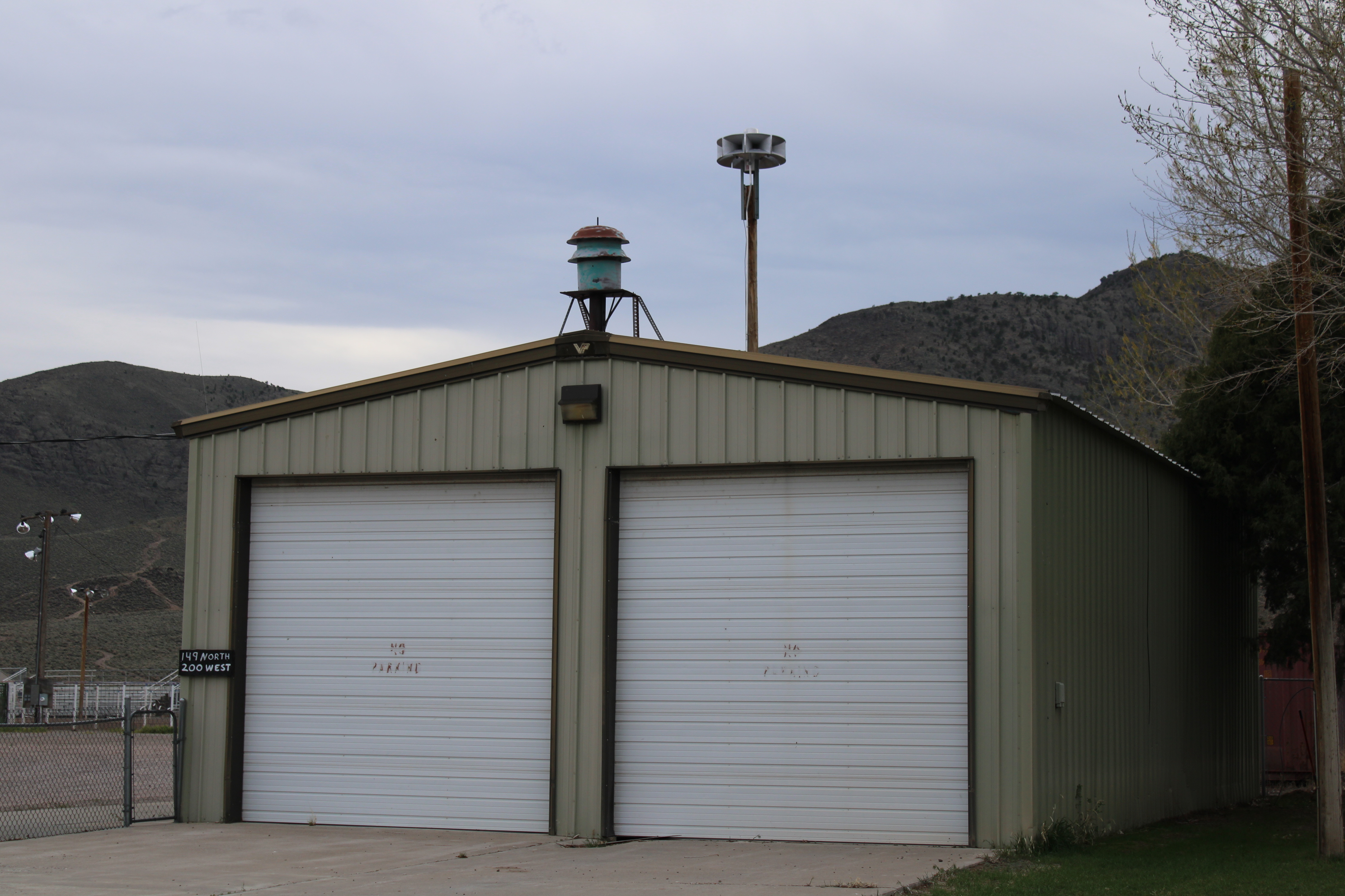
just showing where am trying to get up a radio for the fire department for com's As you can see NO TOWER Or Radio
The Horns are used to call the 4 men and 1 woman to meet here to know where what is
Some things has changed


Amateur radio antennas must not be a hazard to aircraft, so the FCC and the Federal Aviation Administration (FAA) limit the height of an antenna structure to a maximum value.
Towers may exceed this maximum value only with formal notification to the FAA and registration with the FCC. With the notification and registration the tower information can be placed on aviation navigational charts and minimum safe altitude values for aircraft may be adjusted accordingly. It is a win-win for the pilots and the antenna owner.
We will come to the specific maximum allowable height in a moment. First, let’s consider a special case to which this question alludes that is detailed not in FCC Part 97 where the Amateur Radio Service rules and regulations reside, but rather in the FAA Code of Federal Regulations, Title 14, Part 77.9(b). You’ve read that one, right?
In distilled form, this FAA regulation says that if your radio station is within 20,000 feet (3.79 miles) of a public use or military airport you must not erect an antenna structure higher than a calculated value that is based upon the distance of the antenna from the runway.
This makes some sense generally – if you are really close to a runway you want to keep the antenna quite low. If you’re a couple of miles away from the runway a bit higher antenna is probably OK, but how high can you safely and legally go? The height limit is defined as a sloped imaginary surface up from the runway. (With shorter runways the distance for consideration is 10,000 feet, as noted below.)
Here’s what the FAA part actually states, keeping in mind an antenna tower is “a construction or alteration:”
Any construction or alteration that exceeds an imaginary surface extending outward and upward at any of the following slopes:
(1) 100 to 1 for a horizontal distance of 20,000 ft. from the nearest point of the nearest runway of each airport described in paragraph (d) of this section with its longest runway more than 3,200 ft. in actual length, excluding heliports.
(2) 50 to 1 for a horizontal distance of 10,000 ft. from the nearest point of the nearest runway of each airport described in paragraph (d) of this section with its longest runway no more than 3,200 ft. in actual length, excluding heliports.
(3) 25 to 1 for a horizontal distance of 5,000 ft. from the nearest point of the nearest landing and takeoff area of each heliport described in paragraph (d) of this section.
The graphic illustrates an example of a station one mile from a longer runway (>3200 feet) and a station one mile from a shorter runway (<3200 feet). Essentially, the antenna tower must rise no more than 1/100 the distance from the tower to the nearest edge of the runway if the runway is greater than 3200 feet long. If the runway is 3200 feet or less, the tower height may extend up to 1/50 the distance to the nearest edge of the runway.
Graphic depicting the slope from a runway that limits antenna height near an airport.
Of course, the reason for the 20,000 feet (3.79 miles) horizontal range within which this calculation must be considered for a longer runway is due to the general location maximum allowable height of an amateur radio antenna structure without notifying the FAA and registering with the FCC… our question of interest.
When you are 20,000 feet from the nearest runway edge your tower may rise to 20,000 x 0.01 = 200 feet. Similarly, for the shorter runway case, if you are 10,000 feet from the runway the tower may rise 10,000 x 0.02 = 200 feet.
With a heliport, the slope defining the maximum antenna height is 25:1, or the antenna may be 1/25 of the distance to the nearest edge of the heliport. At exactly the 5000 feet distance within which this must be considered, the antenna may again rise up to 200 feet high.
So, if you’re not near the airport, 200 feet is your limit without getting entangled in government red tape. If you are near the airport, get out your measuring tape and calculator.
The answer to General Class question G1B01, “What is the maximum height above ground to which an antenna structure may be erected without requiring notification to the FAA and registration with the FCC, provided it is not at or near a public use airport?” is “C. 200 feet.”
REPEATER WHAT?
What is a Repeater and How Do You Use One to Communicate?
Want to get the best possible coverage in a marginal location, like inside a building or down in a valley? A repeater system can rebroadcast your transmitted and received signals to improve communications.
Repeaters and their antennas are generally located at high elevations—on towers, mountains, or atop tall buildings. To improve signals between radios, they use very efficient high gain antennas, low-loss feedlines and transmitter/receiver combinations that are rated for heavy or continuous duty. A repeater can increase your effective transmitting and receiving coverage, boosting the limited range of your transceiver alone.
How Does a Repeater Work? I think of repeater operation as being much like running a relay race. The transmitting station hands off to the repeater, which receives the signal and passes it onto the receiving station. Since you push the transmit button to send and release to receive, only one side of the conversation is heard at any given time.
Antenna: Most repeaters use one antenna for both transmit and receive. It’s generally a high performance, durable, and efficient antenna with an omnidirectional pattern. They’re placed as high above ground level as possible.
Feedline: Repeaters use a rugged, low-loss cable called hardline. Actually, it looks more like flexible pipe with a center conductor than a cable. Hardline provides lower signal loss than conventional coax, which means more transmit power reaches the antenna and weaker signals can be received by the repeater.
Duplexer: The duplexer separates and isolates the incoming signal from the outgoing and vice versa. It prevents the receiver and transmitter from interfering with one another and helps to reject very strong nearby frequencies or other RF interference from getting into the repeater system. A duplexer typically has two bandpass filters connected in parallel. One filter provides a path between the transmitter and the antenna, and the other provides a path between the antenna and the receiver—there’s no direct path between the transmitter and receiver.
Receiver: Repeater receivers are generally very sensitive and selective, and capture signals that wouldn’t be clearly heard when transmitting directly from radio to radio. It is set to receive the input frequency from radio transceivers.
Controller: This is the brain of the repeater and is essentially a dedicated computer. It handles repeater station ID using either CW or voice and activates the repeater at the appropriate times. It sometimes performs a variety other function, such as giving programmed announcements or linking multiple repeaters.
Transmitter: Most repeaters have a transmitting section containing an exciter and a power amplifier. The exciter retransmits the received audio at the proper frequency and the power amplifier boosts its output.
Keeping Things Separate To use a repeater, a station must use different transmit and receive frequencies. Without having an offset between transmit and receive signals, the repeater would only hear itself when it was transmitting on its receive frequency. For example, 2-meter Amateur Radio repeaters (144-148 MHz) use a +/- 600kHz offset between the receive and transmit frequencies. Repeaters in the 450-470 MHz band use a 5 MHz separation, Repeaters in the 462-467 MHz (GMRS) band Also use a 5 MHz separation, while ones in the 806-869 MHz band use 45MHz separation.
Using an amateur radio repeater pair on 146.94/146.34 MHz as an example, here’s how the process works. Amateur radio operators would transmit their signal on 146.34MHz input frequency, which is received by the repeater. The repeater rebroadcasts the original signal on 146.94 to amateur radios or other receivers listening to the frequency.
Another feature that can help minimize interference and keep the repeater operating smoothly is the subaudible tone (e.g., PL, Motorola’s trademarked tone system). Subaudible (low level) tones can be sent during transmit. The purpose of the tone is to allow you to key up a repeater so you can transmit through it. If your radio is not sending the proper tone, the repeater will not open and relay the signal. Subaudible tones act as a gateway to screen out unwanted signals on receive, such as unauthorized users or signals from distant repeaters on the same frequency that may interfere as a result of band openings.
Hams on RepeatersAmateur radio has been around for more than 100 years, but repeaters didn’t appear on the amateur bands until the late 1950s. Most of today’s Ham repeaters are used for local communications on the VHF/UHF bands. Repeaters are utilized in many areas to extend communication range and provide emergency local communications. GMRS Repeaters are new!
Typically, you’ll find repeaters between 144-148 MHz, 222-225 MHz, 420-450 MHz, (And GMRS 462.-467MHz) and 902-928 MHz Some still exist in the HF/lower VHF band from 29.5-29.7 MHz and 51-54 MHz, but their numbers have declined.
Though FM is still the most popular repeater mode, digital repeaters with DMR, D-STAR (like the DX Engineering employee radio club, N8DXE, new D-STAR repeater), and Yaesu System Fusion capabilities are making inroads. Both digital and analog repeaters can also be connected to online networks such as Echolink, AllStar, Asterisk. Links As in GMRS, Wires II, IRLP and others, allowing worldwide communication capabilities from a handheld radio.
General Mobile Radio Service
Subpart E – General Mobile Radio Service
§ 95.1701 Scope.
This subpart contains rules that apply only to the General Mobile Radio Service (GMRS).
§ 95.1703 Definitions, GMRS.
General Mobile Radio Service (GMRS). A mobile two-way voice communication service, with limited data applications, for facilitating activities of individual licensees and their family members, including, but not limited to, voluntary provision of assistance to the public during emergencies and natural disasters.
Grandfathered GMRS license. A GMRS license held by a non-individual person (i.e., a partnership, corporation, association or governmental unit) as a result of renewals of a GMRS license issued prior to July 31, 1987.
§ 95.1705 Individual licenses required; eligibility; who may operate; cooperative use.
A valid individual license is required to operate a GMRS station. To obtain an individual license, an applicant must be eligible and follow the applicable rules and procedures set forth in this subpart and in part 1 of this chapter, and must pay the required application and regulatory fees as set forth in part 1, subpart G of this chapter.
(a) Eligibility. This paragraph contains eligibility requirements for individual licenses in the GMRS.
(1) Only an individual who is at least 18 years old and who meets the requirements of § 95.305 is eligible to obtain a new individual GMRS license.
(2) Any person that holds a valid individual license is eligible to obtain a renewed license, or a modified license to reflect a change of name or address.
(b) Individual licensee responsibility. The holder of an individual license to operate GMRS stations is responsible at all times for the proper operation of the stations in compliance with all applicable rules in this part.
(c) Individuals who may operate a GMRS station. This paragraph establishes who may operate a GMRS station under the authority of an individual license.
(1) Any individual who holds an individual license may operate his or her GMRS stations.
( 2) Any individual who holds an individual license may allow his or her immediate family members to operate his or her GMRS station or stations. Immediate family members are the licensee’s spouse, children, grandchildren, stepchildren, parents, grandparents, stepparents, brothers, sisters, aunts, uncles, nieces, nephews, and in-laws.
(3) Any individual who holds an individual license may allow anyone to operate his or her GMRS station if necessary to communicate an emergency message.
(4) Any non-individual person that holds a grandfathered GMRS license may allow individuals to operate its grandfathered GMRS station(s) only in accordance with the following paragraphs:
(i) A partnership may allow its partners and employees to operate its GMRS station(s).
(ii) A corporation may allow its officers, directors, members and employees to operate its GMRS station(s).
(iii) An association may allow its members and employees to operate its GMRS station(s).
(iv) A governmental unit may allow its employees to operate its GMRS station(s).
(d) Individual licensee duties. The holder of an individual license:
(1) Shall determine specifically which individuals, including family members, are allowed to operate (i.e., exercise operational control over) its GMRS station(s) (see paragraph (c) of this section);
(2) May allow any person to use (i.e., benefit from the operation of) its GMRS repeater, or alternatively, may limit the use of its GMRS repeater to specific persons;
(3) May disallow the use of its GMRS repeater by specific persons as may be necessary to carry out its responsibilities under this section.
(e) Individual license term. Each individual license in the GMRS will normally have a term of ten years from the date of grant or renewal, and may be renewed pursuant to the procedures in part 1 of this chapter. The FCC may grant a shorter license term at renewal as a sanction for violation of the FCC rules.
(f) Cooperative use of GMRS stations. GMRS licensees may share the use of their stations with other persons eligible in the GMRS, subject to the conditions and limitations in this paragraph.
(1) The GMRS station to be shared must be individually owned by the licensee, jointly owned by the participants and the licensee, leased individually by the licensee, or leased jointly by the participants and the licensee.
(2) The licensee must maintain access to and control over all stations authorized under its license.
(3) A station may be shared only:
(i) Without charge;
(ii) On a non-profit basis, with contributions to capital and operating expenses including the cost of mobile stations and paging receivers prorated equitably among all participants; or
(iii) On a reciprocal basis, i.e., use of one licensee’s stations for the use of another licensee’s stations without charge for either capital or operating expenses.
(4) All sharing arrangements must be conducted in accordance with a written agreement to be kept as part of the station records.
(g) Limitations on grandfathered GMRS licenses. GMRS licenses that were issued prior to July 31, 1987 authorized GMRS station operation at specified locations, on specified channels, and with specified antenna height and transmitter power. Grandfathered GMRS licenses authorize only continued operation of those specific stations by these licensees, at the specified locations, channels, antenna heights and transmitting power. The FCC does not accept applications to modify, assign, or transfer grandfathered GMRS licenses (other than administrative updates to change contact information).
§§ 95.1707-95.1721 [Reserved]
§ 95.1723 GMRS station inspection.
If an authorized FCC representative requests to inspect a GMRS station, the operator must make the station and any station records available for inspection.
(a) A GMRS station includes all of the equipment used in connection with that station.
(b) Station records include the following documents, as applicable:
(1) A copy of each response to an FCC violation notice or an FCC letter.
(2) Each written permission received from the FCC.
(3) Any written agreement regarding sharing arrangements pursuant to § 95.1705(f)(4) of this part.
§§ 95.1725-95.1729 [Reserved]
§ 95.1731 Permissible GMRS uses.
The operator of a GMRS station may use that station for two-way plain language voice communications with other GMRS stations and with FRS units concerning personal or business activities.
(a) Emergency communications. Any GMRS channel may be used for emergency communications or for traveler assistance. Operators of GMRS stations must, at all times and on all channels, give priority to emergency communications.
(b) One-way communications. The operator of a GMRS station may use that station to transmit one-way communications:
(1) To call for help or transmit other emergency communications;
(2) To provide warnings of hazardous road conditions to travelers; or,
(3) To make brief test transmissions.
(c) Travelers assistance. The operator of a GMRS station may transmit communications necessary to assist a traveler to reach a destination or to receive necessary services.
(d) Digital data. GMRS hand-held portable units may transmit digital data containing location information, or requesting location information from one or more other GMRS or FRS units, or containing a brief text message to another specific GMRS or FRS unit.
§ 95.1733 Prohibited GMRS uses.
(a) In addition to the prohibited uses outlined in § 95.333 of this chapter, GMRS stations must not communicate:
(1) Messages in connection with any activity which is against Federal, State, or local law;
(2) False or deceptive messages;
(3) Coded messages or messages with hidden meanings (“10 codes” are permissible);
(4) Music, whistling, sound effects or material to amuse or entertain;
(5) Advertisements or offers for the sale of goods or services;
(6) Advertisements for a political candidate or political campaign (messages about the campaign business may be communicated);
(7) International distress signals, such as the word “Mayday” (except when on a ship, aircraft or other vehicle in immediate danger to ask for help);
(8) Messages which are both conveyed by a wireline control link and transmitted by a GMRS station;
(9) Messages (except emergency messages) to any station in the Amateur Radio Service, to any unauthorized station, or to any foreign station;
(10) Continuous or uninterrupted transmissions, except for communications involving the immediate safety of life or property; and
(11) Messages for public address systems.
(12) The provision of § 95.333 apply, however, if the licensee is a corporation and the license so indicates, it may use its GMRS system to furnish non-profit radio communication service to its parent corporation, to another subsidiary of the same parent, or to its own subsidiary.
(b) GMRS stations must not be used for one-way communications other than those listed in § 95.1731(b). Initial transmissions to establish two-way communications and data transmissions listed in § 95.1731(d) are not considered to be one-way communications for the purposes of this section.
§§ 95.1735-95.1739 [Reserved]
§ 95.1741 GMRS antenna height limits.
GMRS station antennas must meet the requirements in § 95.317regarding menaces to air navigation. See § 95.317 and consult part 17 of the FCC’s Rules for more information (47 CFR part 17).
§ 95.1743 Minor GMRS operators.
Operators under the age of 18 will not be held personally responsible, pursuant to § 95.343, for improper operation of a GMRS repeater or base station. The holder of the individual license under which the minor operates is solely responsible for any improper operation that occurs while an individual under the age of 18 is operating the station.
§ 95.1745 GMRS remote control.
Notwithstanding the prohibition in § 95.345, GMRS repeater, base and fixed stations may be operated by remote control.
§ 95.1747 GMRS automatic control.
Notwithstanding the prohibition in § 95.347, GMRS repeater stations may be operated by automatic control.
§ 95.1749 GMRS network connection.
Operation of a GMRS station with a telephone connection is prohibited, as in § 95.349. GMRS repeater, base and fixed stations, however, may be connected to the public switched network or other networks for the sole purpose of operation by remote control pursuant to § 95.1745.
§ 95.1751 GMRS station identification.
Each GMRS station must be identified by transmission of its FCC-assigned call sign at the end of transmissions and at periodic intervals during transmissions except as provided in paragraph (c) of this section. A unit number may be included after the call sign in the identification.
(a) The GMRS station call sign must be transmitted:
(1) Following a single transmission or a series of transmissions; and,
(2) After 15 minutes and at least once every 15 minutes thereafter during a series of transmissions lasting more than 15 minutes.
(b) The call sign must be transmitted using voice in the English language or international Morse code telegraphy using an audible tone.
(c) Any GMRS repeater station is not required to transmit station identification if:
(1) It retransmits only communications from GMRS stations operating under authority of the individual license under which it operates; and,
(2) The GMRS stations whose communications are retransmitted are properly identified in accordance with this section.
§§ 95.1753-95.1559 [Reserved]
§ 95.1761 GMRS transmitter certification.
(a) Each GMRS transmitter (a transmitter that operates or is intended to operate in the GMRS) must be certified in accordance with this subpart and part 2 of this chapter.
(b) A grant of equipment certification for the GMRS will not be issued for any GMRS transmitter type that fails to comply with the applicable rules in this subpart.
(c) No GMRS transmitter will be certified for use in the GMRS if it is equipped with a frequency capability not listed in § 95.1763, unless such transmitter is also certified for use in another radio service for which the frequency is authorized and for which certification is also required. No GMRS transmitter will be certified for use in the GMRS if it is equipped with the capabilities to operate in services that do not require equipment certification, such as the Amateur Radio Service. All frequency determining circuitry (including crystals) and programming controls in each GMRS transmitter must be internal to the transmitter and must not be accessible from the exterior of the transmitter operating panel or from the exterior of the transmitter enclosure.
(d) Effective December 27, 2017, the Commission will no longer issue a grant of equipment authorization for hand-held portable unit transmitter types under both this subpart (GMRS) and subpart B of this part (FRS).
(e) Effective December 27, 2017, the Commission will no longer issue a grant of equipment authorization under this subpart (GMRS) for hand-held portable units if such units meet the requirements to be certified under subpart B of this part(FRS).
The GMRS is allotted 30 channels – 16 main channels and 14 interstitial channels. GMRS stations may transmit on any of the channels as indicated below.
(a) 462 MHz main channels. Only mobile, hand-held portable, repeater, base and fixed stations may transmit on these 8 channels. The channel center frequencies are: 462.5500, 462.5750, 462.6000, 462.6250, 462.6500, 462.6750, 462.7000, and 462.7250 MHz.
(b) 462 MHz interstitial channels. Only mobile, hand-held portable and base stations may transmit on these 7 channels. The channel center frequencies are: 462.5625, 462.5875, 462.6125, 462.6375, 462.6625, 462.6875, and 462.7125 MHz.
(c) 467 MHz main channels. Only mobile, hand-held portable, control and fixed stations may transmit on these 8 channels. Mobile, hand-held portable and control stations may transmit on these channels only when communicating through a repeater station or making brief test transmissions in accordance with § 95.319(c). The channel center frequencies are: 467.5500, 467.5750, 467.6000, 467.6250, 467.6500, 467.6750, 467.7000, and 467.7250 MHz.
(d) 467 MHz interstitial channels. Only hand-held portable units may transmit on these 7 channels. The channel center frequencies are: 467.5675, 467.5875, 467.6125, 467.6375, 467.6625, 467.6875, and 467.7125 MHz.
§ 95.1765 GMRS frequency accuracy.
Each GMRS transmitter type must be designed to comply with the frequency accuracy requirements in this section under normal operating conditions. Operators of GMRS stations must also ensure compliance with these requirements.
(a) The carrier frequency of each GMRS transmitter transmitting an emission with an occupied bandwidth greater than 12.5 kHz must remain within 5 parts-per-million (ppm) of the channel center frequencies listed in § 95.1763 under normal operating conditions.
(b) The carrier frequency of each GMRS transmitter transmitting an emission with an occupied bandwidth of 12.5 kHz or less must remain within 2.5 ppm of the channel center frequencies listed in § 95.1763 under normal operating conditions.
§ 95.1767 GMRS transmitting power limits.
This section contains transmitting power limits for GMRS stations. The maximum transmitting power depends on which channels are being used and the type of station.
(a) 462/467 MHz main channels. The limits in this paragraph apply to stations transmitting on any of the 462 MHz main channels or any of the 467 MHz main channels. Each GMRS transmitter type must be capable of operating within the allowable power range. GMRS licensees are responsible for ensuring that their GMRS stations operate in compliance with these limits.
(1) The transmitter output power of mobile, repeater and base stations must not exceed 50 Watts.
(2) The transmitter output power of fixed stations must not exceed 15 Watts.
(b) 462 MHz interstitial channels. The effective radiated power (ERP) of mobile, hand-held portable and base stations transmitting on the 462 MHz interstitial channels must not exceed 5 Watts.
(c) 467 MHz interstitial channels. The effective radiated power (ERP) of hand-held portable units transmitting on the 467 MHz interstitial channels must not exceed 0.5 Watt. Each GMRS transmitter type capable of transmitting on these channels must be designed such that the ERP does not exceed 0.5 Watt.
§ 95.1769 [Reserved]
§ 95.1771 GMRS emission types.
Each GMRS transmitter type must be designed to satisfy the emission capability rules in this section. Operation of GMRS stations must also be in compliance with these rules.
(a) Each GMRS transmitter type must have the capability to transmit F3E or G3E emissions.
(b) Only emission types A1D, F1D, G1D, H1D, J1D, R1D, A3E, F3E, G3E, H3E, J3E, R3E, F2D, and G2D are authorized for use in the GMRS. Equipment for which certification is sought under this subpart may have capabilities to transmit other emission types intended for use in other services, provided that these emission types can be deactivated when the equipment is used in the GMRS.
§ 95.1773 GMRS authorized bandwidths.
Each GMRS transmitter type must be designed such that the occupied bandwidth does not exceed the authorized bandwidth for the channels used. Operation of GMRS stations must also be in compliance with these requirements.
(a) Main channels. The authorized bandwidth is 20 kHz for GMRS transmitters operating on any of the 462 MHz main channels (see § 95.1763(a)) or any of the 467 MHz main channels (see § 95.1763(c)).
(b) Interstitial channels. The authorized bandwidth is 20 kHz for GMRS transmitters operating on any of the 462 MHz interstitial channels (see § 95.1763(b)) and is 12.5 kHz for GMRS transmitters operating on any of the 467 MHz interstitial channels (see § 95.1763(d)).
(c) Digital data transmissions. Digital data transmissions are limited to the 462 MHz main channels and interstitial channels in the 462 MHz and 467 MHz bands.
§ 95.1775 GMRS modulation requirements.
Each GMRS transmitter type must be designed to satisfy the modulation requirements in this section. Operation of GMRS stations must also be in compliance with these requirements.
(a) Main channels. The peak frequency deviation for emissions to be transmitted on the main channels must not exceed ± 5 kHz.
(b) 462 MHz interstitial channels. The peak frequency deviation for emissions to be transmitted on the 462 MHz interstitial channels must not exceed ± 5 kHz.
(c) 467 MHz interstitial channels. The peak frequency deviation for emissions to be transmitted on the 467 MHz interstitial channels must not exceed ± 2.5 kHz, and the highest audio frequency contributing substantially to modulation must not exceed 3.125 kHz.
(d) Overmodulation. Each GMRS transmitter type, except for a mobile station transmitter type with a transmitter power output of 2.5 W or less, must automatically prevent a higher than normal audio level from causing overmodulation.
(e) Audio filter. Each GMRS transmitter type must include audio frequency low pass filtering, unless it complies with the applicable paragraphs of § 95.1779 (without filtering).
(1) The filter must be between the modulation limiter and the modulated stage of the transmitter.
(2) At any frequency (f in kHz) between 3 and 20 kHz, the filter must have an attenuation of at least 60 log (f/3) dB more than the attenuation at 1 kHz. Above 20 kHz, it must have an attenuation of at least 50 dB more than the attenuation at 1 kHz.
§ 95.1777 GMRS tone transmissions.
In addition to audible and subaudible tones used for receiver squelch activation and selective calling, to establish or maintain communications with specific stations or to access repeater stations (see § 95.377), GMRS transmitters may also transmit audio tones for station identification (see § 95.1751).
§ 95.1779 GMRS unwanted emissions limits.
Each GMRS transmitter type must be designed to comply with the applicable unwanted emissions limits in this section.
(a) Emission masks. Emission masks applicable to transmitting equipment in the GMRS are defined by the requirements in the following table. The numbers in the attenuation requirements column refer to rule paragraph numbers under paragraph (b) of this section.
Emission types filter Attenuation
requirements
A1D, A3E, F1D, G1D, F2D, F3E, G3E with audio filter (1), (2), (7)
A1D, A3E, F1D, G1D, F3E, G3E without audio filter (3), (4), (7)
H1D, J1D, R1D, H3E, J3E, R2E (5), (6), (7)
(1) Filtering noted for GMRS transmitters refers to the requirement in § 95.1775(e).
(2) Unwanted emission power may be measured as either mean power or peak envelope power, provided that the transmitter output power is measured the same way.
(b) Attenuation requirements. The power of unwanted emissions must be attenuated below the transmitter output power in Watts (P) by at least:
(1) 25 dB (decibels) on any frequency removed from the center of the authorized bandwidth by more than 50% up to and including 100% of the authorized bandwidth.
(2) 35 dB on any frequency removed from the center of the authorized bandwidth by more than 100% up to and including 250% of the authorized bandwidth.
(3) 83 log (fd ÷ 5) dB on any frequency removed from the center of the authorized bandwidth by a displacement frequency (fd in kHz) of more than 5 kHz up to and including 10 kHz.
(4) 116 log (fd ÷ 6.1) dB or 50 + 10 log (P) dB, whichever is the lesser attenuation, on any frequency removed from the center of the authorized bandwidth by a displacement frequency (fd in kHz), of more than 10 kHz up to and including 250% of the authorized bandwidth.
(5) 25 dB on any frequency removed from the center of the authorized bandwidth by more than 50% up to and including 150% of the authorized bandwidth.
(6) 35 dB on any frequency removed from the center of the authorized bandwidth by more than 150% up to and including 250% of the authorized bandwidth.
(7) 43 + 10 log (P) dB on any frequency removed from the center of the authorized bandwidth by more than 250%.
(c) Measurement bandwidths. The power of unwanted emissions in the frequency bands specified in paragraphs (b)(1)through (4) of this section is measured with a reference bandwidth of 300 Hz. The power of unwanted emissions in the frequency range specified in paragraph (b)(5) of this section is measured with a reference bandwidth of at least 30 kHz.
(d) Measurement conditions. The requirements in this section apply to each GMRS transmitter type both with and without the connection of permitted attachments, such as an external speaker, microphone, power cord and/or antenna.
§§ 95.1781-95.1785 [Reserved]
§ 95.1787 GMRS additional requirements.
Each hand-held portable unit transmitter type submitted for certification under this subpart is subject to the rules in this section.
(a) Digital data transmissions. GMRS hand-held portable units that have the capability to transmit digital data must be designed to meet the following requirements.
(1) Digital data transmissions must only be initiated by a manual action by the operator, except that GMRS units may automatically respond with location data upon receiving an Interrogation request from another GMRS or FRS unit.
(2) Digital data transmissions must not exceed one second in duration.
(3) Digital data transmissions must not be sent more frequently than one digital data transmission within a thirty-second period, except that a GMRS unit may automatically respond to more than one interrogation request received within a thirty-second period.
(4) The antenna must be a non-removable integral part of the GMRS unit.
(5) GMRS units must not be capable of transmitting digital data on the 467 MHz main channels.
(b) [Reserved]
§ 95.1789 [Reserved]
§ 95.1791 Sales of GMRS/FRS combination radios prohibited.
(a) Effective September 30, 2019, no person shall be permitted to manufacture or import, sell or offer for sale any radio equipment capable of operating under both this subpart (GMRS) and subpart B (FRS) of this chapter.
§§ 95.1793-95.1899 [Reserved]
for more information visit eCFR :: 47 CFR Part 95 Subpart E — General Mobile Radio Service


